Nate's Computer: large printer kit
For printers with at least a 300 × 300 × 300 mm build volume (made for the Bambu Lab H2D Pro). Every part fits within 300 × 300 × 300 mm.
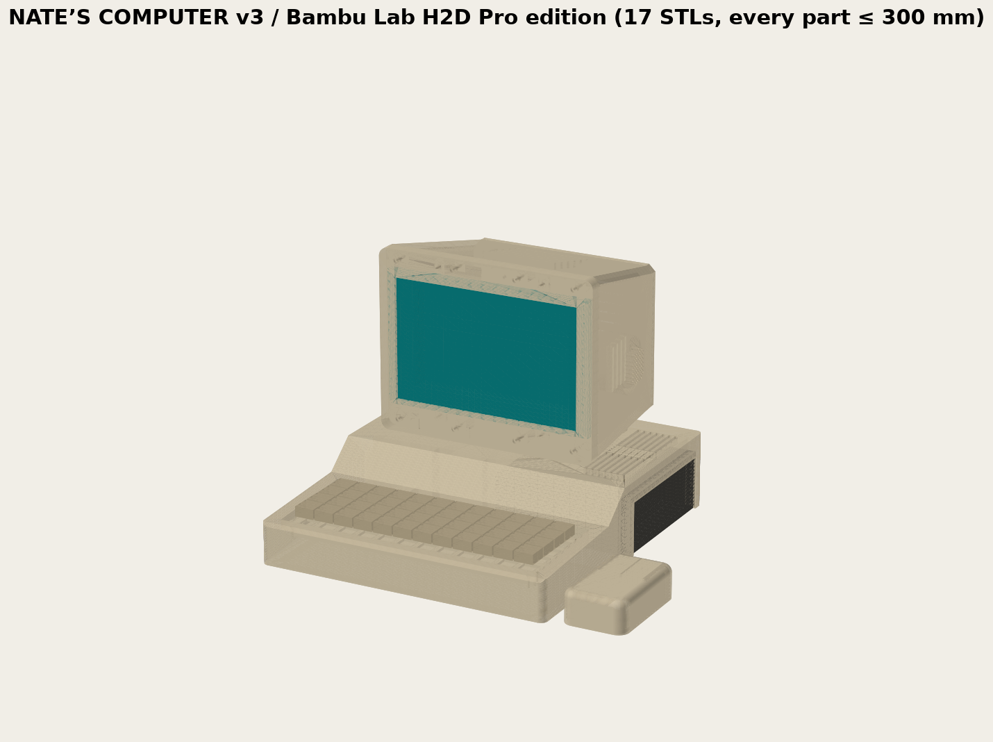
1. What's in the kit
The parts in stl/ are already turned the right way up for printing. Import them at 100 %.
| Part | File | Prints | Size (mm) | Joined by |
|---|---|---|---|---|
| Base (keyboard and PC bay) | base |
1 | 270 × 300 × 68 | — |
| Floor | floor |
1 | 122 × 135 × 4 | 8 × M3 × 10 countersunk screws |
| Keyboard plate | kb_plate |
1 | 244 × 92 × 3 | 12 × M2 × 6 countersunk screws |
| Pedestal | pedestal |
1 | 150 × 100 × 12 | 4 × M4 × 35 bolts |
| Monitor bezel | mon_bezel |
1 | 205 × 165 × 12 | 8 × M3 × 20 into the shell |
| Monitor shell | mon_shell |
1 | 205 × 165 × 132 | — |
| Monitor rear cover | mon_rear_cover |
1 | 175 × 135 × 6 | 4 × M3 × 12 |
| Screen clamp | mon_screen_clamp |
4 | 16 × 10 × 3 | M3 × 10 |
| Speaker cap | spk_cap |
2 | 52 × 52 × 3 | 3 × M2 × 6 each |
| Badge | badge_blank |
1 | 49 × 9 × 1 | Double-sided tape |
| Mouse | mouse_bottom, mouse_top |
2 | 58 × 96 × 30 | 4 × M2 × 8 |
| Test pieces | FIT_… |
5 | small | — |
2. What you need
- Electronics, screws and other hardware: see PARTS.md. This kit needs:
- 8 floor screws instead of 14
- 4 floor feet instead of 8
- Filament: about 2 kg of ABS (or ASA) for the whole kit. The PC runs inside, so ABS throughout — base, monitor and keyboard and mouse too, so it's all one material. Settings: FILAMENT.md.
- No glue or pins: every part is one piece, and parts are joined with screws.
- Tools:
- calipers
- small screwdrivers and hex keys
- a craft knife
- a hot glue gun
3. Print settings
Use the settings in FILAMENT.md for your filament. For this kit, also:
- Print with one nozzle, one filament per part.
- Add a 5 mm brim on the base, and keep the door closed until it has cooled (ABS warps if it cools fast).
- Add supports only under:
- the monitor shell's screw bosses
- the two speaker rings inside
mon_shell - the bay deck inside
base: tree supports from the bed (they come out through the open bottom) - the vent and side-window tops in
base, if the slicer flags them - ABS, ASA or PC: set the shrinkage first (FILAMENT.md, step 3).
4. Print and check the test pieces
Print these first, in the filament you'll use for the rest.
| Test piece | Check | If it doesn't fit |
|---|---|---|
FIT_holes_1p8_2p0_2p2_2p6_3p4_4p4 |
1.75 mm filament pushes snugly into the 2.0 hole. M2.5 and M3 screws bite in the 2.2 and 2.6 holes. M3 and M4 slide through 3.4 and 4.4. | Change PIN_D and the hole sizes in build.py |
FIT_switch_plate_2x2 |
4 switches click in and don't rattle | Change SW_CUT in build.py |
FIT_keyboard_ledge_corner |
The keyboard board drops into the corner with about 1 mm to spare | Check the board against SOURCES.md |
FIT_speaker_pod |
A speaker sits flat against the grille and the cap screws on | Check the speaker against SOURCES.md |
FIT_screen_corner |
The screen corner sits in the pocket | Check the screen against SOURCES.md |
Then connect the PC, screen, keyboard board, speakers and mouse on the bench and check they all work.
5. Print the parts
Print each part as it is in the file. Don't rotate it.
6. Assemble
A. Base
- Remove the supports from inside the bay.
- Fit the 40 mm fan behind the rear grille, blowing out, with 4 × M3 × 16 screws from outside.
- Stick the sound card, amplifier and USB hub inside the left half with foam tape. Keep the speaker wires away from the HDMI cable.
- Run the keyboard USB cable from the keyboard well, through the channel and tunnel, into the left half.
- Screw on the floor (8 × M3 × 10).
- Stick on the rubber feet:
- 4 under the front
- 4 on the floor
- one 8 mm foot in the rear-right corner
B. Keyboard
- Stick 6 × 3 mm bumpons on the floor of the keyboard well, away from the switch sockets.
- Drop in the keyboard board, USB-C at the back. Plug the USB cable in through whichever back pocket lines up.
- Screw the plate onto the ledge (12 × M2 × 6).
- Push the switches through the plate into the board, then fit the keycaps.
C. Monitor
- Lay the bezel face down. Fit the 0.8 mm gasket, then the screen.
- Fit the 4 clamps with soft pads (M3 × 10). Run the screen cables down through the slot in the bottom.
- Push the bezel and screen into the shell from the front and fix them with 8 × M3 × 20.
- Speakers:
- From inside the shell, push a speaker into each side ring, front against the grille.
- Pass the wires through the cap's centre hole and screw the cap on (3 × M2 × 6).
- Seal the hole and the rim with hot glue.
- Run the speaker wires down through the slot in the bottom.
- Stand the pedestal on the base and the monitor on the pedestal. Bolt them together with 4 × M4 × 35. The bolt heads go under the base deck; the washers and nuts go inside the monitor.
- Screw on the rear cover (4 × M3 × 12).
- Stick the badge into the recess on the bezel.
D. Mouse
- Take the donor mouse apart. Keep its board, sensor lens, switches, battery holder and receiver.
- Fix the board on
mouse_bottombetween the rails, with M2 screws or hot glue. The sensor must sit over the window at the donor's original height. Shim with tape if needed. - Check that the two pegs under the buttons sit just above the mouse switches. If they don't, see SOURCES.md.
- Close it with 4 × M2 × 8 and stick on the skates.
E. Connect the PC
- Stand the PC on the desk, front panel facing right.
- Plug into the PC's rear ports:
- power brick
- Ethernet, if used
- HDMI to the screen
- screen power, on its own port
- amplifier power, on its own port
- sound card
- USB hub (keyboard, touch and fan)
- Run the power brick cable and any outside cables out through the notch at the bottom of the rear wall.
- Lower the base over the PC so its front panel shows through the side window.
- Switch on with the PC's own power button in the side window.
- Do the heat check in FILAMENT.md.